Product model and nameplate
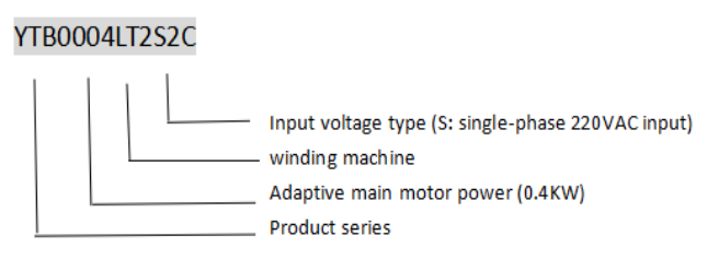
YTB0004LT2S2C frequency changer Figure 2-1 shows an example of the product model. ,figure 2-2 shows the nameplate.(Take Single-phase input 0.4KW frequency changer as an example).

Figure 2-1 Product Model Example
2.2 YTB0004LT2S2C Product list
Model | Winding motor | Overfeed motor | Cooling way | ||
Power(KW) | Rated output current(A) | Power(KW) | Rated output current(A) | ||
YTB0004LT2S2C | 0.4 | 2.5 | 0.1 | 0.6 | Since the cold |
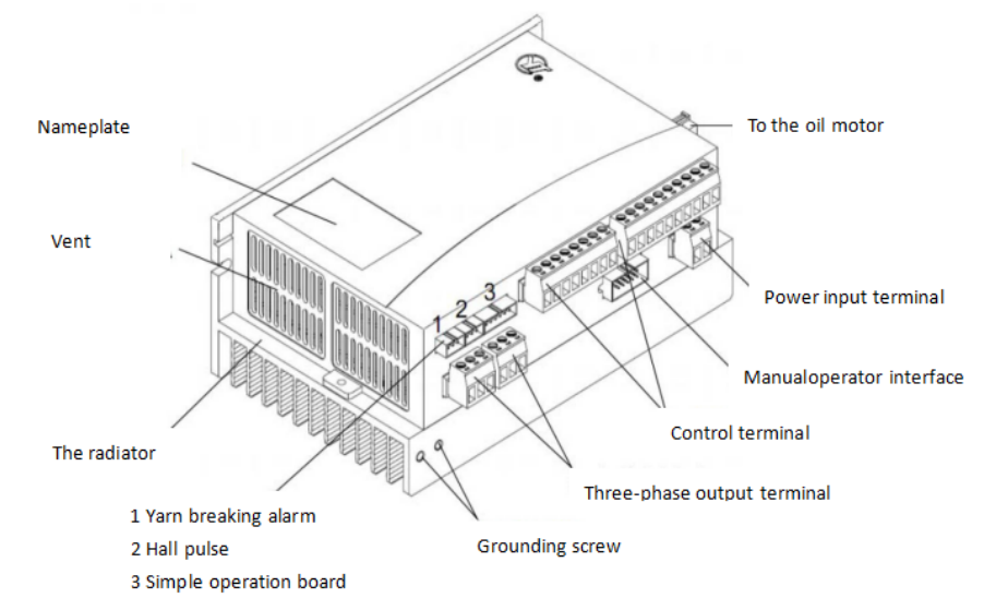
2.3Product appearance

Figure 2-2 Exterior structure
Installation and wiring
3.1 Installation
3.1.1 Installation direction and space
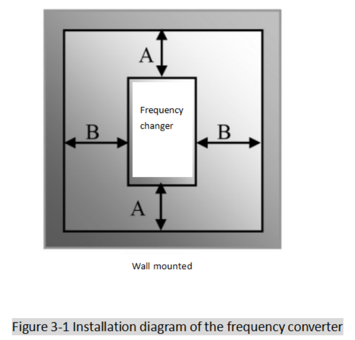
In order to facilitate heat dissipation of the frequency converter, the frequency converter should be installed in the vertical direction (as shown in Figure 3-1), and the surrounding ventilation space should be ensured.
Table 3-1 shows the clearance size of inverter installation (recommended value)

Table 3-1 Gap size
Frequency converter type | Gap size | |
Wall mounted | A≥150mm | B≥50mm |
3.1.2 Installation environment
No rain, water droplets, steam, dust and oily dust; No corrosion,inflammable gas and liquid; No metal particles or metal powder.
The ambient temperature ranges from -10 ° C to +50 ° C.
Less than 1000 meters above sea level.
The relative humidity of the environment must be less than 90%, and there is no water condensation.
No strong electromagnetic interference.
The vibration intensity is below 0.5 g (acceleration)
If the inverter is installed in the control cabinet, it should ensure smooth ventilation between the control cabinet and the outside world.


